The Danglepoise
Motivation
In the dying years of the 20th century, the “rise and fall” light fitting became briefly popular. You know the type: a counterweight (or spring) balances out the weight of the lantern so that the lamp can be moved up and down. I’ve always thought that these were rather neat. You can leave them up near the ceiling for general room illumination, lower them a bit to create a more intimate atmosphere, or pull them right down for focused task work. Couple a rise and fall pendant with that other 1970s lighting must-have, the dimmer switch, and you have a really flexible lighting system.
I recently found myself in need of some lighting, and wanted to replicate this neatness. It became rather complicated.
Why not just buy a rise and fall pendant lamp and a dimmer switch, and have done with it? Three reasons. Firstly, modern decorative lighting seems to operate in a very price-sensitive market, which has driven manufacturers to engineer out costs everywhere that they can. This generally results in a certain flimsiness in a large number of domestic light fittings. That works pretty well for something that you can simply install and forget; the disconcerting wobbliness will bother you for a few minutes while you install the fitting, and is then irrelevant until you come to remove it. For something that is expected to move reliably and safely, though, wobbliness and flimsiness make me unhappy.
This first problem could be avoided by looking at antique rise and fall fittings: these are generally more solid. However, finding one in good condition is reasonably difficult, and finding five in good condition that match is nigh on impossible. Five, you say? Ah yes. Following some recent renovations, we’ve ended up with a reasonably long dining table, ideal for entertaining or for a big family game of Kingdom Death : Monster (caution: not suitable for families). Lighting this adequately needs, I reckon, about five lights in a row. So the antique approach is out.
Thirdly, finally, and possibly most fundamentally: I really like putting electric motors in things. It’s not that I’m a fan of pointless complication (although… actually that’s probably a whole other post!). It’s just that having something move automatically is just inherently more satisfying than having to move that thing yourself. Or at least I think so.
Having convinced myself that there’s nothing on the market that would satisfy my (admittedly niche) requirements, I did what any sensible person would do: I gave up and tried to ignore it. I failed. This post is an attempt to document my persistent failure to ignore the urge to make lights go up and down with motors.
Research
On slip rings
So, what’s the best way to arrange for a lamp to move up and down? My first thought was to suspend the lamp from some suitable flex, and wind the other end of the flex around a drum attached to a motor. This seems logical, but makes getting power to the lamp somewhat tricky: as the drum turns, we need some way of maintaining electrical connectivity. The solution to this is a “slip ring”, which is basically some circular conductive rings on one side of a spinny thing arranged such that they’re in contact with some… contacts on the other side of the spinny thing. I’d say “stop me if I’m getting too technical”, but to be honest, there’s no stopping me now.
Anyway, slip rings are definitely a thing. There are quite a wide range of them, but we have a couple of extra constraints: not having thought through exactly what sort of lamp we’re going to dangle from this thing, it seemed best to use a conventional mains lamp holder (you can get lots of different types, after all), rather than trying to find exactly the right low-voltage solution at the outset. So we need to run mains over the slip ring, and furthermore, we’d really like the lamp not to flicker when it moves. That means that we need quite a good slip ring.
In my searches for slip rings, I found three main types: moderately-priced low-voltage slip rings, cheap mains-rated slip rings for vacuum cleaners (the ones with self-rewinding cables, presumably), and really expensive high-quality slip rings. These last seem to be used mainly by defense companies: tank turrets(!), seeker heads on missiles, that sort of thing. I hadn’t set a budget for this project yet, but when potential suppliers are oriented toward the heavier end of the military-industrial complex, it’s time for a re-think.
I re-thought.
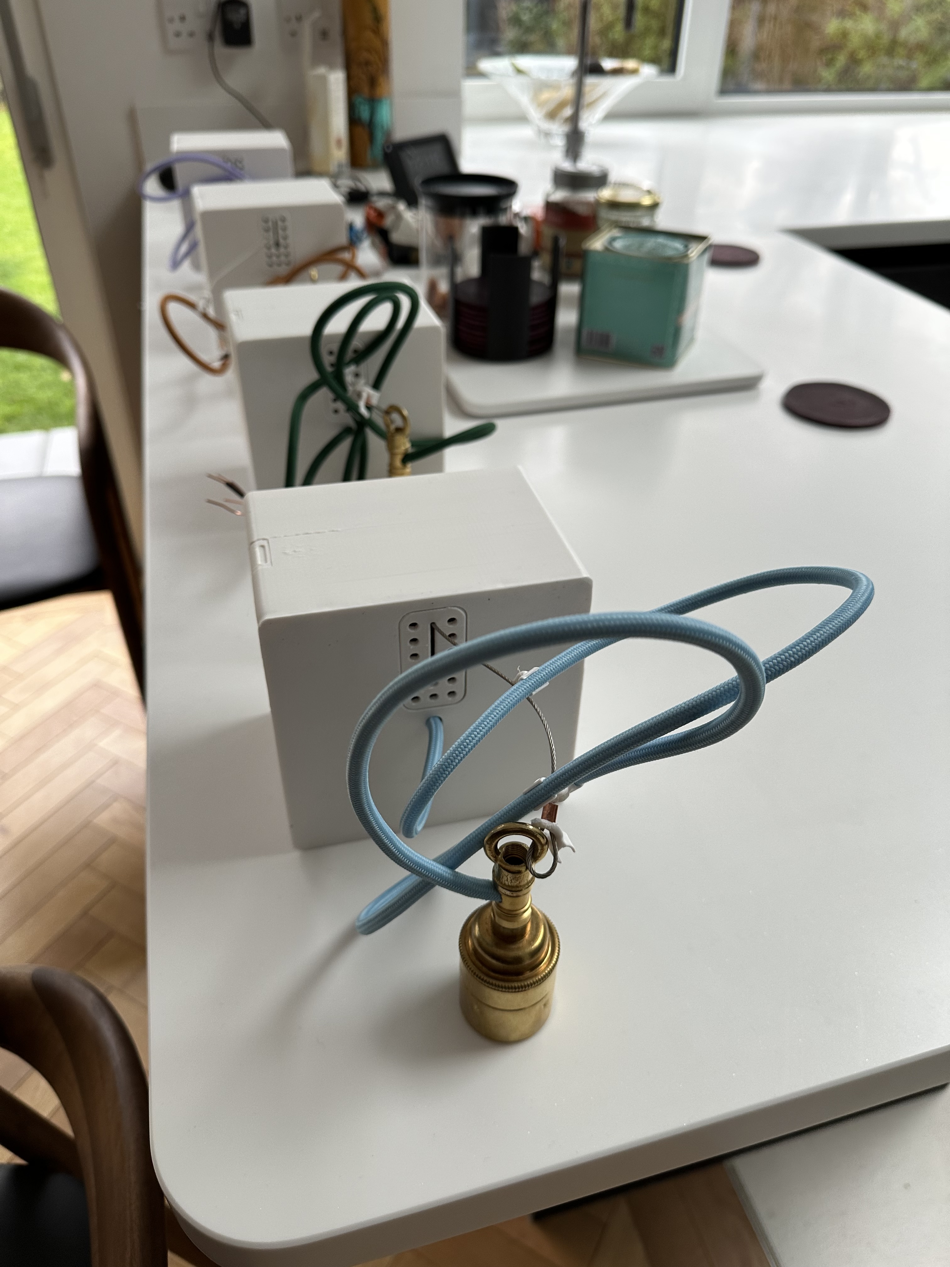
If I can’t spin the cable around, I can’t really wind it up. If I can’t wind the cable, I’m probably going to need to wind something else in order to turn the rotational movement of a motor into linear movement to make the lamp rise and fall. That’s not so hard, but then what do I do with the flex, which is still going to be necessary in order to provide power to the lamp? I could just leave it loose, forming a big loop when the lamp is at the top of its motion, but that will a) look pants and b) tend to push the lamp off-axis (also looking pants). So we need a way to make sure that the flex fills a more compact space when it doesn’t have much distance to cover, but still allows extension when the lamp falls. I came up with these (some of which printed better than others):
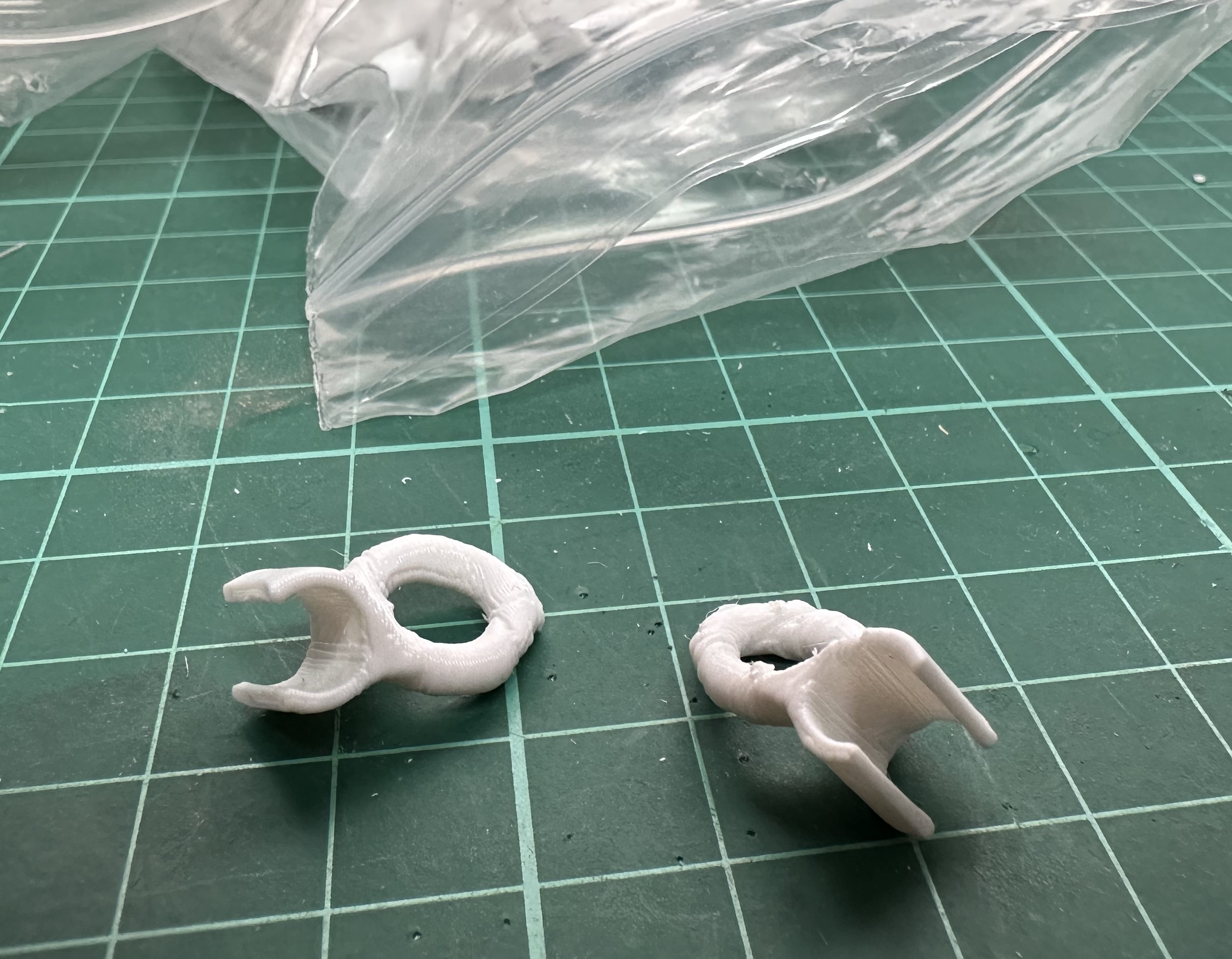
The lamp fitting is suspended from a steel cable. This seemed like a good choice for something that can be wound: strong, flexible, and readily available (in my case, from the very helpful TECNI in Somerset). I settled for a cable 1.5mm in diameter, which has a Minimum Breaking Load of 130kg - probably a bit much, for these purposes, but easier to get hold of than anything thinner. The world-shaking innovation, here, is the pairs of little plastic clips. These thread onto the cable (the steel one) and then clip onto the flex. Get this: the orientation of the flex-clip relative to the cable loop is offset by either +90º or -90º! Radical. The upshot of this is that the flex adopts a pleasing zig-zag configuration as the cable retracts.
I prototyped this using a plywood mount and a hand-pulled cable, and convinced myself that it works. I had a photo of it working, but I’ve lost it, so here’s a short clip of the finished product doing some zig-zagging:
Rude Mechanicals
OK, that’s the dangly bit out of the way. Next to think a bit harder about the whole moving-up-and-down-under-electronic control part. As mentioned above, motors are good. Of course, there are lots of different types of electric motor, with various sizes and capabilities, so before doing any proper design work, I probably ought to choose one. It’s worth noting that these lamps probably don’t need to move particularly fast, and despite the cable’s strength, aren’t intended to be particularly heavy. So I shouldn’t need a really big motor - that’s good, as we’re going to be attaching the whole assembly to the ceiling at some point (more on this later), so we don’t want anything too heavy.
Small is good, then. Except, not too small; we can always trade speed for torque using a gearbox, but that’s noise and complexity that I don’t really want to deal with. So it would be nice to have a motor with enough torque to directly drive the cable-winding drum. I’d also like to be able to position the lamp reasonably accurately. High torque, relatively low speed, precise control? It sounds like we’re in stepper-motor territory. For those rare readers who aren’t particularly into electric motors (I’m trying not to judge), stepper motors are the kind of motors usually used in 3D printers. They have two (or more) separate coils, arranged in such a way that energising them in a particular sequence causes the motor to rotate through a single “step”. Reversing the sequence makes them take a step in the opposite direction. Steps are usually fairly small, of the order of a degree or less, so it takes lots of steps to rotate through 360º. This makes them really good at precise positioning, not so great at really high-speed operation, and pretty high-torque.
Stepper motors also have another interesting property: they’re good at holding a position. One coil will be energised at every possible position, providing a “holding torque” which resists the motion of the shaft. This sounds pretty useful for our application, as we want the lamps to stay where they’re put, but it also means that they use very nearly as much power at standstill as they do when they’re spinning. That seems… inelegant. Wasteful. Not fun. So we need something more. Some kind of brake? Yeah, that’d do it. Such things are indeed available, but are not necessarily available for the size of stepper motor you want (and you can get steppers in almost any size). I selected a motor and brake assembly that seemed about right, which was promptly discontinued by the manufacturer half way through the project.
Is there an app for that?
Heroic in my ignorance of the finer points of mechanical design, I deferred further thought of how everything was going to fit together until later on. The last key piece to nail down (not literally: that’s still a mechanical concern) was the electronics, and more specifically what kind of microcontroller to use. I have for the longest time been a fan of the Electric Imp platform - indeed it formed the basis of my major commercial hardware project, the Fruit, several hundred of which are still in use 7 years later. However, the company behind it has changed hands a number of times, which makes it look a bit questionable from a longevity point of view, and in any case lots of my fellow techies told me at the time that we’d have been better off using an ESP32. I can see the superficial similarities: they’re both powerful embedded microcontrollers with wifi support. Electric Imp go rather further in terms of their security model and ease-of-use, but ESP32s are more popular, and cheaper. I gave in, and decided to build the electronics around a TinyPICO, which is a particularly well-designed variation on the ESP32 theme.
Design
Off we go then. We’ve got the ability to dangle, a stepper-and-brake widget, and a microcontroller. Where to start? On the somewhat-arrogant assumption that I’d be able to eventually make the firmware work eventually, I decided to start with the electronics. Except, of course, it would be silly to try to design the electronics without knowing how much space I’ve got to play with, so I actually started with the rough outlines of the physical design. The key component was clearly the stepper motor, as it’s relatively big and heavy - it would need a rigid mounting point, and some air-flow around it for cooling purposes. It would also need to attach to some kind of winch arrangement to drive the cable. After a bit of spreadsheet-work, I established that a winch drum with a diameter slightly less than that of the motor would give adequate torque and also be able to spool up a few metres of cable without being too wide, which suggested a nice simple stack of brake : motor : drum as the major assembly to design around.
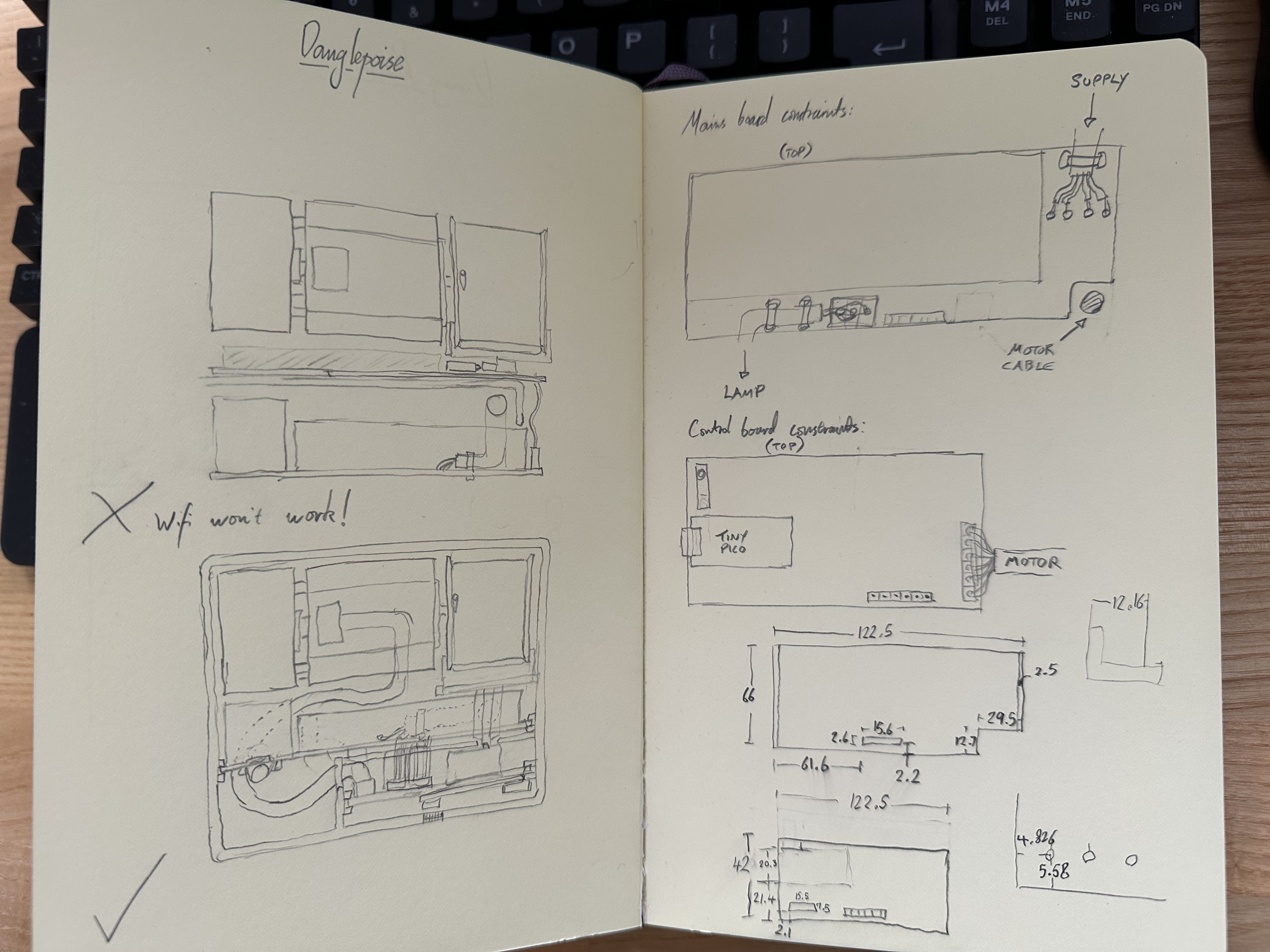
I spent a while vacillating on whether I’d need any auxiliary cable management; I considered adding additional rollers so that the cable could exit the finished unit from the absolute centre (purely for aesthetic reasons), but decided in the end that the wear and complexity weren’t worth the hassle. Instead, the cable exit would be centred in one axis and offset on the other, with the cable descending directly from the winch drum without passing over any other load-bearing part. This needed the motor assembly to have one edge just over the centre-line of the enclosure, which immediately implied a cuboid outer box leaving a roughly 140 x 60 x 80mm void for the electronics (and quite a few mechanical details to be worked out later).
Electronics
With a rough space-budget worked out, it was nearly time to break out KiCad, but first I needed to work out what, exactly, to try to fit into that space. The TinyPICO had already been selected, but that certainly can’t drive a stepper motor directly, and a few other ideas had emerged whilst I’d been kicking the concept around. The electronics, I decided, would have to do the following things:
- Have a self-contained mains-rated power supply
- Be really quite unlikely to catch fire
- Have a separate power input for the lamp fitting itself (allowing the unit to function as a lamp even if all the worky bits fail - optimistic, eh?)
- Be able to switch the lamp supply on and off (no dimming required, though; all the units would be wired to an external C-Bus dimmer channel)
- Drive the solenoid brake
- Drive the motor itself, ideally smoothly and quietly
- Indicate overall status via an LED
- Power the TinyPICO
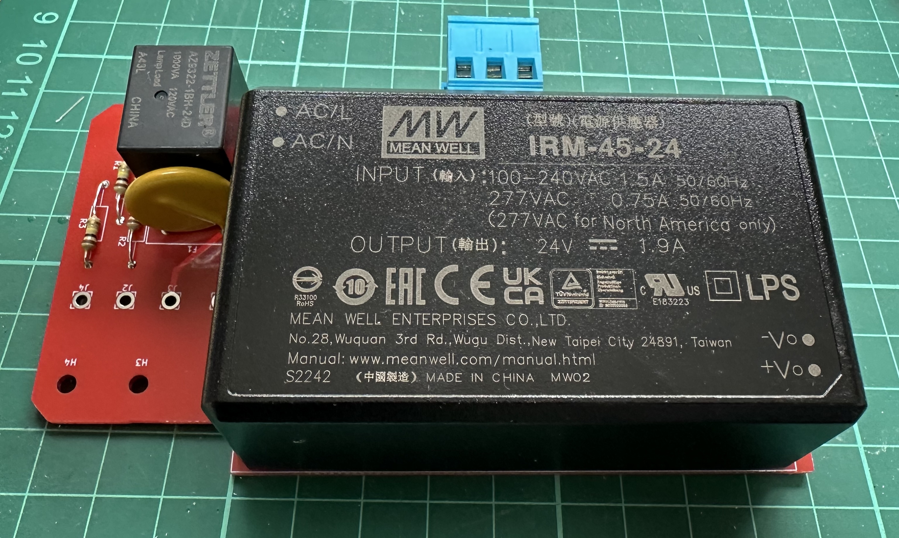
The second of these seemed like the most important, which meant choosing a good mains power supply module and treating it with respect. As always with power supplies, the key factors are voltage and current. Stepper motors aren’t too fussy about voltage, but the solenoid brake is specced for 24 Volts, so 24 Volts is what we will give it. The rest of the electronics would be happier with 5V, so we’ll need a further regulator of some sort. A power budget of around an Amp for the motor, another Amp for the brake (quite high!) and half an Amp for the rest of the electronics (this is generous) works out at 2.5A, or an overall 60 Watts at 24 Volts. Sounds like a job for the straightforwardly-named IRM-60-24, a fully-encapsulated mains power supply from Mean Well.
Because I’m a scaredy-cat when it comes to mains, and also because of the size of the IRM-60-24, I decided to put all the mains-voltage stuff on one PCB, and everything else on a separate one, connected by header pins. The only other components to fit onto the mains board were thus a relay to allow the lamp supply to be switched, and a polyfuse to protect the relay in case of a short-circuit in the lamp flex. It was quite straightforward to knock this together in KiCad, then lay out a suitable two-layer PCB. Gratifyingly, this part of the design needed no further refinement… unlike almost everything else.
The control board was a little more involved. In theory, you can drive a stepper motor with nothing more than a handful of MOSFETS and a lookup table, but that needs quite precise timing control (which I wasn’t sure about achieving, given that the ESP32 was going to have quite a lot of other stuff going on), and is in any case fairly crude. The state-of-the-art for stepper motor control involves chopper algorithms that either scale the voltage presented to the motor coils in order to reduce operating noise, or very rapidly react to velocity and load in order to damp out resonances in the motor. Microstepping is also common, allowing ultra-fine positional control, which helps to avoid jerkiness at low speeds. These techniques all sound horribly analogue, so I started looking for a dedicated motor-control chip to take care of it all for me.
The TMC2208 from Trinamic appeared to fit the bill: it has a lot of trademarked features such as MicroPlyer™ and StealthChop2™, not to mention the probably-helpful-sounding SpreadCycle™. These tick all the “fancy control algorithm” boxes, and the part can drive up to 2A per coil at voltages up to 36V, whilst needing few external parts. It has a handy UART interface. The only slight down-side is that it’s only available as a QFN part: these are quite fiddly to hand-assemble, particularly if your hot-air gun is on the wonk (as mine is), so it probably meant having someone else assemble the board, and also using a 4-layer PCB for thermal reasons. Not the end of the world, but to convince myself that this part would indeed do the trick, I ordered a development kit.
In summary: yes, the TMC2208 can definitely drive the stepper motor I had in mind. Excellent. That was fun. Now to finish off the Bill of Materials for the control board. We’d need a power supply for the low-voltage side of the TMC2208 and the TinyPICO (converting the 24V we get from the mains board down to 5V), and also a driver for the solenoid brake (and indeed for the lamp-supply relay over on the other board). I picked the BTS7090 for this, which is almost certainly overkill but, being an automotive part, seemed designed to be quite tolerant of various thermal and power-supply abuses. Oh, we also needed a limit switch, to determine when the cable had been wound up to the top of its travel.
After quite some time spent poring over datasheets, I convinced myself that I’d come up with a workable schematic. That led to the pleasantly zen task of routing all the tracks; quite satisfying, but I’m sure I was told back in the 1990s that this would be a fully-automated activity by now… anyway, after the usual feeling that I’d missed something important, but not being able to find out what it was, I sent the designs to the almost improbably helpful JLCPCB for manufacturing (and partial assembly of the control board). Design-for-Manufacturing is a vast and complex topic, which I largely ignored for this project - I could certainly have made life easier by choosing more readily-available parts, but for a proof-of-concept such as this, it’s probably not a good use of time.
Mechanical
I’ve been trying to find an interesting angle to use when writing about mechanical design, but the best I can do is 1.5º - that’s the draft angle applied to the edge of the chassis, to ensure that it’s possible to remove it from the casing. It’s not actually that interesting. What was more interesting was the sheer complexity of the design I ended up with; I’ve been working with 3D modelling and 3D printing for several years now, but this was by far the most complicated design I’ve attempted. As is, I think, often the case, a lot of the complexity came from a desire for outward simplicity: I really wanted the body of the main unit to be visually simple, and as compact as possible. This meant trying to pack the internal components together quite tightly, and minimising the number of features that would be visible on the bottom or sides of the unit. Whether I was successful in this will become more apparent later on (spoiler: not really, in my opinion), but let’s walk through the initial design first to understand where the gremlins were hiding.
From the rough block diagram above, it’s clear that we have three main parts that need to be held in relation to each other, and also protected from pokey fingers. These are the mains PCB, the control PCB and the motor. Whatever we end up doing about a winch will be attached to the motor shaft, so that doesn’t really need too much thought. It would also be a good thing if all the parts stay firmly attached to the ceiling during use: the motor and brake assembly weighs just under 1kg, so I’m quite keen to avoid it falling on anyone’s head. However, it also needs to be possible to remove the unit for maintenance (and inevitable debugging).
My thinking converged on attaching the motor to a rigid chassis, that would interlock with a mounting plate that would be screwed to the ceiling. A latch would be provided to ensure that these two parts couldn’t accidentally cease to be interlocked. The chassis would also allow us to use screws to attach an outer casing to the chassis, without these being visible once the unit was mounted. Neat. It was here that I made my first big mistake: because the casing would be quite deep, I thought it would be a good idea to have the PCBs simply slot into it from above. These could then be secured by the chassis, which could remain quite thin - and also wouldn’t have to have any protuberances on its lower surface. This appealed to me, on the basis of being easy to print without supports.
In retrospect, I should have attached the PCBs to the chassis, not the casing. It would have vastly simplified the process of assembly, and made the workings much easier to debug. That would have been much more useful than the saving in plastic achieved by having a thin chassis. A useful lesson for next time.
Anyway, this discussion would be much easier to follow with pictures, so let’s see some:
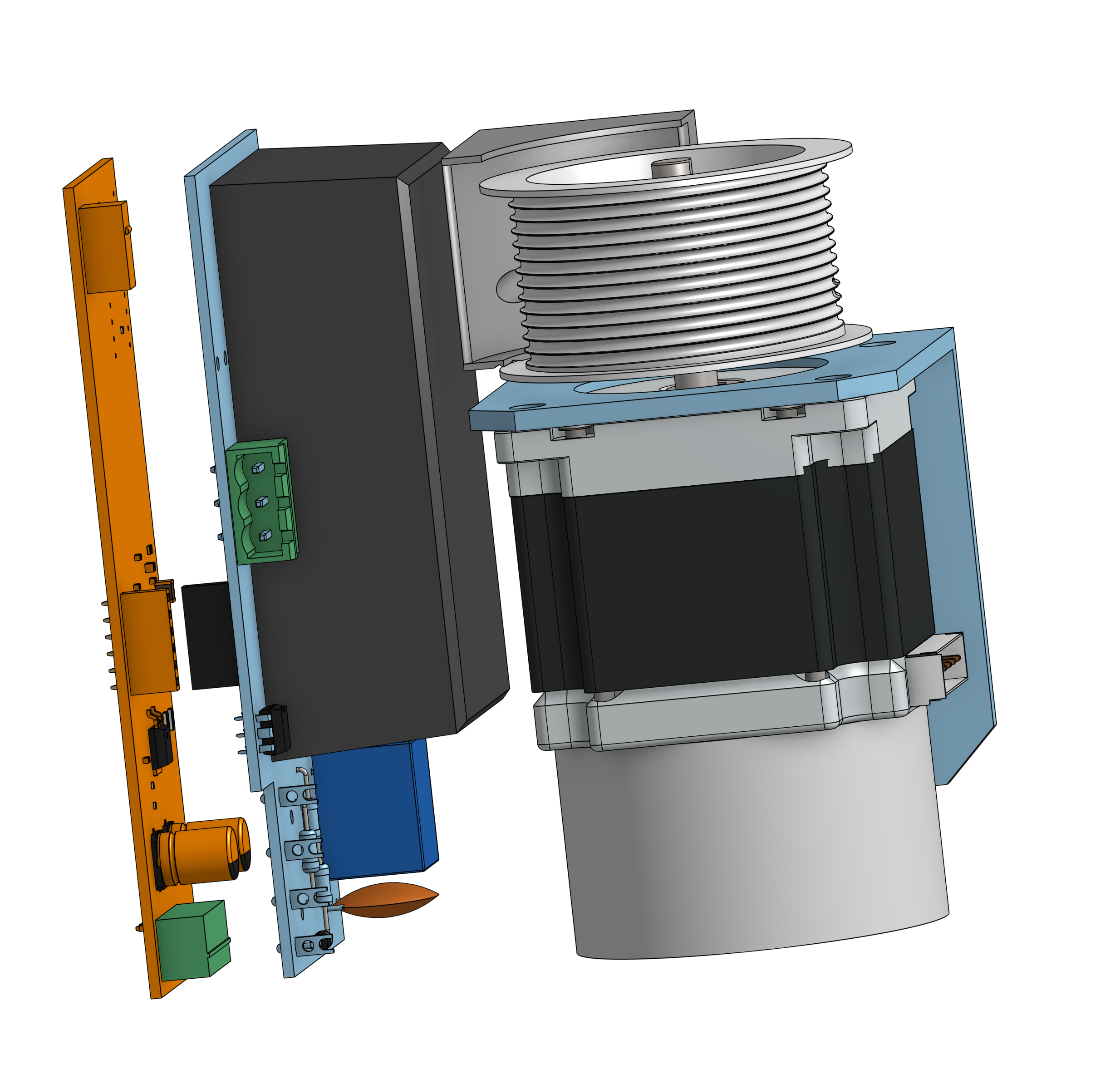
These are the main parts. Oh, I should probably point out that I used the excellent OnShape for all this: it’s an absolute pleasure to use, compared to all the other CAD systems I’ve tried. I know I’m only scratching the surface of its capabilities, but just getting the basics absolutely right makes it infinitely less frustrating than, say, Fusion 360. Without it, this process would have felt a lot like work, rather than something I’m doing for fun. Anyway, those parts look rather lost, just floating in space, so here’s an early version of the chassis:
Early chassis
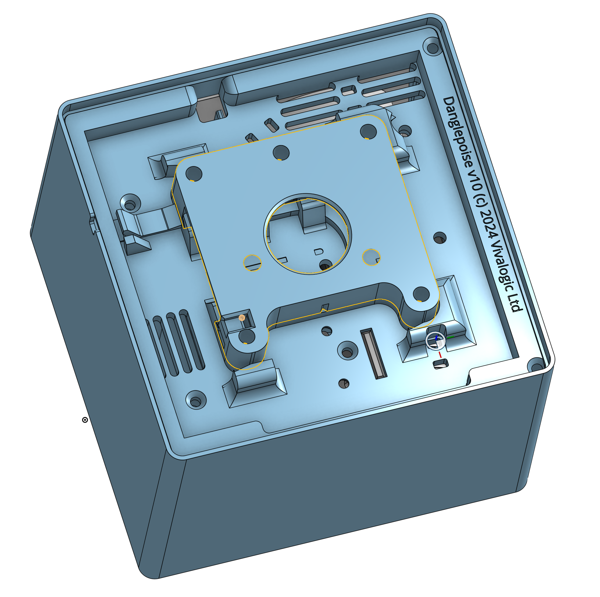
The finger-type arrangement in the middle is intended to interlock with the mounting plate, which looks like this:
Early mounting plate
The mounting plate attaches to the ceiling via the screw holes (I provided several, as you never know what you’re going to hit), and can be lined up neatly using the alignment notches. The lambda-shaped clip on the chassis engages with the mounting plate, making sure that the two parts can’t be separated unless you depress the clip with a suitable tool. The rest of the features are mainly an attempt at cable management, which would later undergo heavy revision so I won’t waste time on them now.
On winches
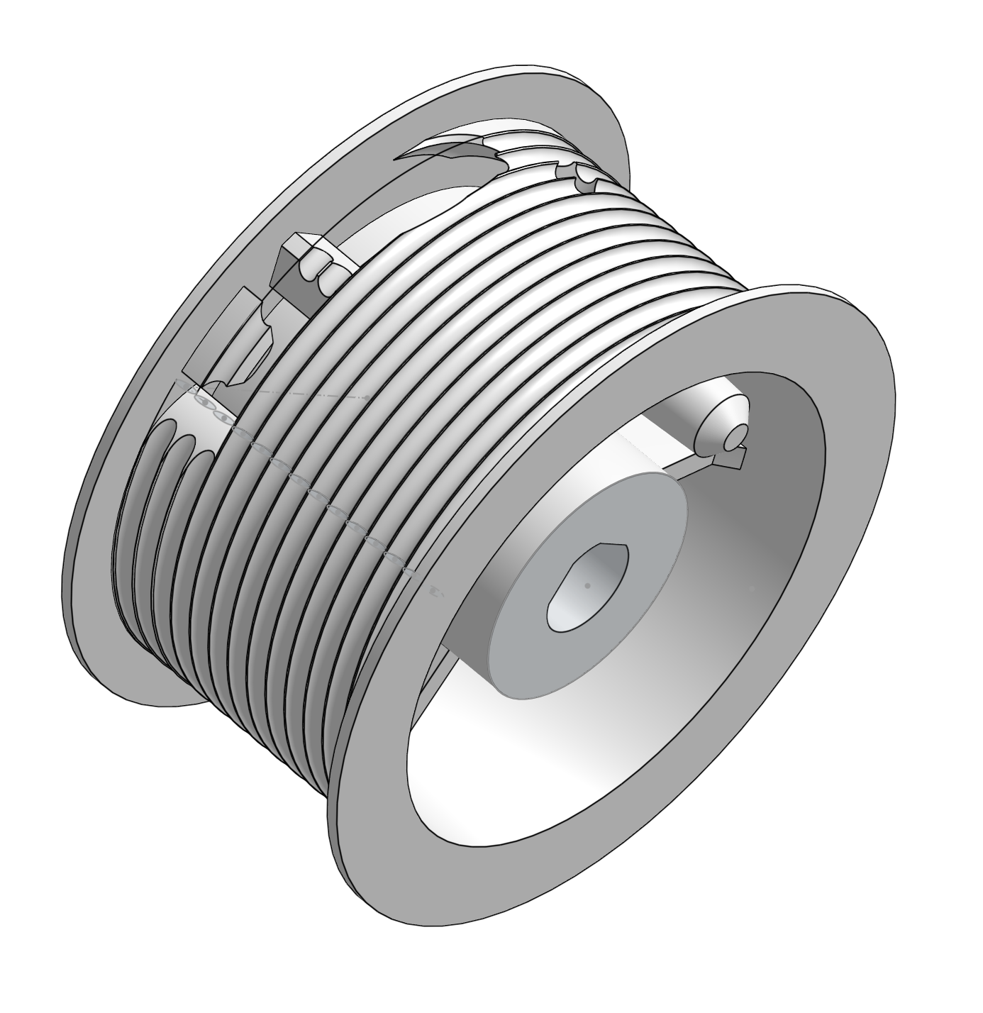
There’s surprisingly little material available on the Internet on the subject of winch design, so I had to tackle things largely from first principles. As such, I made an interesting series of mistakes, and would take a fundamentally different approach if I were to tackle this design again. The first challenge was to securely attach the cable to the drum. Tight bends are bad for braided cables, so I started by forming a cylinder and then providing a hole in this through which the cable would be led to an attachment point inside the cylinder. The end of the cable would be formed into a loop using a crimp-on ferrule, and then slipped over a cunningly-shaped mounting post that would hold it in position. The post doesn’t have to be massively strong, as there would always be a few turns of cable on the drum in use, and the friction between these turns and the drum itself would provide the holding force rather than the post itself - but even so, I tried to make it as solid as possible.
Another concern was to try to make the cable wind neatly onto the drum, particularly to avoid it all bunching up on top of itself. Received wisdom seems to be that this is best tackled in the first layer by shaping grooves into the drum for the cable to spiral into. I wasn’t sure how effective this would be, but spent a fun afternoon on it anyway, coming up with a design that subtracted a swept helical tube from the surface of the cylinder to form a nice spiral groove (with appropriate lead-in and lead-out). Add some flanges at either end of the drum to prevent the cable slipping off, and we’re pretty much done:
Other mechanical bits
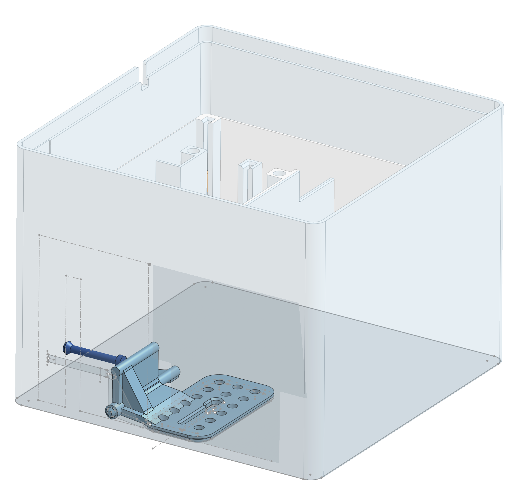
As mentioned previously, we need to know when the lamp fitting has been winched to the top of its travel, to provide a reference point from which to calculate distances, and also to stop the motor smashing the lamp into the main unit with catastrophic results. This is one of the parts that actually iterated pretty rapidly between mechanical and electronic design, but I’ll discuss it here to avoid jumbling up the narrative too much. Basically, the idea was that the cable would exit the casing through a narrow slot, aligned to be tangential to the edge of the drum. The area surrounding the slot would be hinged, such that if anything larger than the cable impacted this area it would pivot in such a way as to depress a microswitch on the PCB. As the cable slot is on a centre-line of the casing and the control PCB is all the way over on the edge, this necessitated a lever, pusher and switch arrangement that ends up reminding me vaguely of the hammer, stirrup and anvil of the human ear:
Fitting this into the casing involved a bit of fiddling around with the internal bulkhead (which was there to make sure that the steel cable cannot come into contact with any mains-voltage parts, as well as providing rigidity), but apart from that the casing design was, as a first attempt, reasonably straightforward. Honest.
Early casing
The flex exits from the centre of the bottom face, secured internally by a strain-relief clamp, and the casing as a whole (including the PCBs) is attached to the chassis using brass screw-thread inserts. These are very easy to use (just heat them up with a soldering iron and push them in), and provide a secure mechanical connection; I’ll be using them again in future.
With that, in theory, the mechanical design was done. In practice… read on. But first, let’s turn to firmware.
Firmware
It turns out that those who assured me that the ESP32 is as capable a platform for embedded development as Electric Imp were… just. plain. wrong. Comparatively speaking, it’s a dog. Don’t get me wrong, it’s a very capable device, and all the pearl-clutching about its potential security vulnerabilities is probably spurious, and of course it’s very cheap, but… the developer experience is about as pleasant as trying to prune a rose bush using only a nail file: do-able, but it’s going to hurt.
The fundamental difficulty with developing for the ESP32 is the fabled Gulf of Execution. In simple terms, it takes too bloody long to get feedback after making a change, because deploying new code is something that you really have think about (rather than being incidental and transparent, as it should be). I must admit that I hadn’t done a lot of reading into the specifics of building and deploying code on this platform, which was a mistake. I had naively assumed that things had improved in the decade or so since Electric Imp hit the market, and that people wouldn’t be putting up with having to plug a serial cable into a device that already has on-board WiFi, just to program it. How wrong I was.
I’ll return to this topic (as it is irritating, and I don’t like being reasonable about things that obviously ought to be better), but first a brief digression on languages. There are lots of languages that will target the Xtensa CPU cores used by the ESP32, including, intriguingly, Rust. I like Rust. It’s a bit of a head-scratcher at times, but once you’ve got that head around the borrow-checker, it gives you lots of lovely compile-time guarantees; you can be pretty confident that if your code compiles, it will not only run but probably do what you expect, which is a genuinely confidence-inspiring property. So, my starting point for developing the firmware for the Danglepoise was to set up the toolchain for cross-compilation of Rust from a Mac to an ESP32. This was pretty straightforward.
What was less obvious was the level of support for the various ESP32 peripherals (including, critically, WiFi). Documentation for this was, at the time that I started looking at it, fairly uneven (I know it’s improved since). Further confusion emerged from not knowing whether it was best to go for a bare-metal implementation (#![no_std], in Rust-speak), or whether to take the resource hit of using the Rust runtime. This is a fairly nuanced decision, and it’s unfortunate that prospective Rust embedded developers have to grapple with it before they’ve had much of a chance to build familiarity with the trade-offs.
In any case, after experimenting with a few different approaches, I ended up being able to get WiFi up and running on a bare-metal ESP32. However, finding higher-level libraries (such as an HTTP server, for example!) that would work without the standard library was deeply frustrating. Again, this has probably improved a lot in the last couple of years, but in any case none of the tooling seemed really set up for deploying new code over-the-air, which I considered to be a show-stopper.
In the course of reading quite a few pages on the ESP32, it became apparent that there were a lot more people using MicroPython than were using Rust. Large numbers of hobbyists usually bring developer-experience improvements, and I had read of some people successfully using a tool called WebREPL to deploy code to an ESP32 over wifi. Peripheral support also seemed to be extremely good. Now, I’ve used Python a bit in the past (it runs the lighting in my wardrobe, for example, and also the pantry door), and it’s… OK. I don’t really understand why so many people think it essential for machine learning work, and my personal opinion is that significant whitespace is pure evil, but lots of people get along with it so it can’t be too bad.
After a little more research, it became apparent that an IDE called Thonny (link) was the tool of choice for MicroPython development, mainly because it supports deployment over WebREPL. I spent a bit of time trying to replicate this capability using IntelliJ IDEA (my tool of choice), but it proved to be too much effort for my then-extant levels of motivation - which were fairly low, as I’d hoped to be writing some actual firmware by this point.
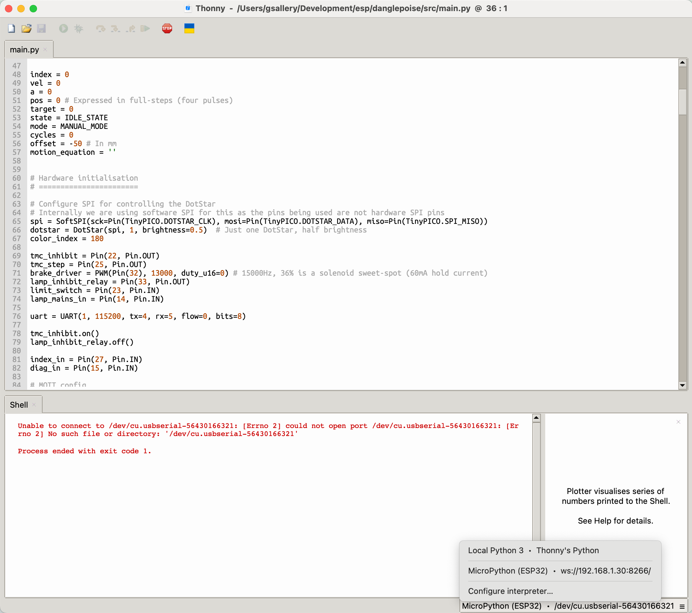
After satisfying myself that I could, at last, send code from Thonny to the TinyPICO over-the-air, I wrote a little bit of code to flash the onboard LED on and off, and then started thinking about how to talk to the TMC2208. At this point, the PCBs arrived in the post.
Development
With PCBs, components, first-draft printed parts and a vague idea of how to approach the firmware, there now began many, many months of iterative kerfuffle. Some of this was highly educational. It all took a lot longer than expected. For the sanity of the reader, I’ll try to boil this period down to the key discoveries.
- The mains PCBs were good, and did what was expected of them as soon as I populated the boards and powered them up (using a 3D-printed box to allow me to switch the motor/lamp supplies separately with a degree of safety). Great.
- The control PCBs were more fiddly. They arrived with the surface-mount parts already in place (including that fiddly TMC2208), leaving me to place the through-hole parts by hand. Most of these were easy, apart from the TinyPICO; I had hoped to be able to place blobs of solder under the part and then join it to the PCB using a hot-air gun (basically, a poor-man’s BGA), but the untimely demise of my hot air gun meant that I actually had to solder 20 short pieces of tinned-copper wire to both the part and the board to serve as headers. This was surprisingly fiddly, as the pieces of wire tended to drop out of the holes when you heated the opposite side of the assembly. I developed a technique of cutting the wires long, soldering one end, and then holding the other with a pair of tweezers whilst I soldered the other end, which worked well but was quite time-consuming.
- Another problem with the control PCBs was that the TinyPICO didn’t seem to want to talk to the TMC2208 over a serial connection. I could send simple pulses on the STEP and DIR pins, which gives limited control of the motor, and the motor would indeed step appropriately (something of a relief). However, more sophisticated control of the driver for things like setting MicroPlyer parameters, reading error codes and tweaking current limits can only be achieved via a serial link, which initially proved spectacularly uncommunicative. My initial suspicion was that I was sending the wrong checksums, as the motor controller datasheet didn’t go into a lot of detail on exactly how to calculate these. There was some C pseudocode for checksum generation, but it’s always possible that I’d translated this into MicroPython incorrectly. Luckily, Trinamic provide a handy spreadsheet with (among other things) a checksum calculator; once I’d found this, I could feel happy that I’d got the checksums right, but still further confused that I still couldn’t talk to the controller. Eventually, after much probing with the oscilloscope and noticing that the transmitted serial voltages looked a bit weak at the controller end of the connection, I realised that a resistor was in the wrong place: the TMC2208 uses a single pin for both transmit and receive, so if you’re attaching this to two separate UART pins it’s good practice to put a 1k resistor in the receive line. I’d put it in the transmit line by mistake, which was attenuating the signal. After some fine work with a microscope and a scalpel, I moved the resistor to the right place and data began to flow. I’d have to repeat this procedure on each of the control boards.
- With more nuanced control of the motor now working, I could start tuning the motion parameters. Quite rapidly, this led to the realisation that a push-fit drum wasn’t going to cut it: the motor shaft gets a bit warm in operation, and printable plastics have a fairly low melting point, so after half an hour of testing the drum would start to slip on the shaft. Amazon were happy to sell me some appropriately-sized motor shaft adaptors in aluminium (at least I assume that they were happy: at the markup they were charging, they should have been), which fixed securely onto the shaft with a grub screw and then could be screwed into the (redesigned) drum.
- The limit switch mechanism needed a few tweaks, including (critically) the application of grease to the little push rod that goes between the lever and the microswitch. The mounting points for the lever also needed some adjustment, to make sure they didn’t pop out if pushed too hard.
- While implementing the limit switch logic (MicroPython has interrupt handlers: hooray!), it became apparent that getting code to the TinyPICO over the air was a little bit flaky. Transfers would sometimes abort part-way, needing a reset of the device, and very occasionally they’d leave it in an inconsistent state that had to be overwritten over the USB-C connection. Not too troublesome while everything was in parts on the bench, but… worrying.
- Speaking of parts… getting some of them together proved fiddly. The limit switch parts need to be assembled with pliers, because I can’t get my hands into the tiny gap between the casing and the bulkhead. Sliding the PCBs into their guide slots usually worked well, but sliding them out again could result in bent pins if the two PCBs skewed relative to each other. Which they were likely to do, as the mains PCB has some fairly stiff wires attached to it, which apply noticeable torque. Getting these wires to stay where they’re meant to be is also non-trivial, especially when trying to close up the unit (they tended to get caught on things you can’t quite see and don’t have enough fingers to poke back into place). Another good argument for not putting the PCBs in the wrong half of the box, really.
- The TinyPICO has a little LED to show when it’s charging. When it’s running from a 5V supply, it just shows that it has power, which is not particularly helpful. I must have imagined reading that there was a PCB trace on the TinyPICO that could be cut to disable this, but there isn’t. Tiny slivers of electrical tape provided a partial solution, but the best fix turned out to be a dab of Sugru.
- With all the parts fitted together, I rigged up a temporary mounting rig in the shed so that I could develop the firmware some more. The first order of business was to get a web server running, so that commands could be sent to the Danglepoise remotely. This wasn’t particularly hard, but did reveal a couple more code deployment issues, one minor, one less so. The tedious-but-not-particularly-significant one is that using a library in MicroPython means remembering to copy the file to the target device manually (and getting the name right). This is a one-off activity, so it’s merely clunky, but it’s not very polished. A bigger problem is that running a web server really impedes the performance of the WebREPL: file transfer failures became even more common, and it was also frequently impossible to halt the device so that new code could be executed. This basically rendered it impossible to deploy over-the-air, meaning a revision to the casing so that I could get access to the TinyPICO to plug in the USB cable. Disappointing. The ESP32 really does seem to be lacking some quality-of-life features.
- Talking of the casing, revisions to this started to take quite a lot of time: it’s a tall part, and I wanted a reasonably fine finish, so it ended up taking around 12 hours per print. I probably got through about 2.5kg of filament over the course of the project, mainly on the casings. Incidentally, I used PETG for the casing, as it has a slightly higher melting point and is somewhat impact-resistant compared to PLA.
- Now onto the biggest mechanical problem: persuading the cable to stay in the right place. Under tension, the cable stays neatly and tidily coiled around the drum. If, however, you even think about letting it go slack at any point, it will jump off the drum and wind itself around the nearest obstruction (usually the motor shaft). You may not discover this until you next move the motor, at which point it will seize up and probably make some very unpleasant noises. Assembling the casing is a two-handed process, so the “proper” technique (developed after many issues with immovable winches) is to put something heavy on the cable, drape it off the end of the workbench, and then be very very careful to only move the chassis and casing in such a way as to maintain the tension in the cable. This is, to put it mildly, a faff. Some kind of brake mechanism acting directly on the cable would be a much better idea, as well as being potentially lighter, quieter and less current-thirsty than the solenoid brake on the motor shaft. Something to think about for next time.
- When it came to actually attaching a unit to the ceiling, a couple of things became apparent. Firstly, there was nowhere near enough clearance to get the actual mains cables on the supply side to lay flat. If they don’t lay flat, there’s no way to get the interlocking fingers to engage, and so no way to attach the unit to the ceiling. The best place to discover this is definitely not at the top of a step ladder, where it gets surprisingly warm (thermal stratification in action!). The second discovery was that the “easy to use” push-fit mains connectors I’d chosen were anything but: they’re surprisingly tall, require quite a lot of force and are prone to losing the little actuator-lever mouldings that are the only safe way of disconnecting them. A redesign of the printable parts addressed the first discovery, but not the latter, which remains awkward.
- RCBOs are generally a good idea, but don’t like sharing a neutral, for what turn out to be perfectly obvious reasons when you actually stop and think about them. Some small (supply-side) electrical adjustments were necessary before I could power up the lamps.
- I got quite a long way into the development process before melting my first unit. Eeek. It wasn’t a catastrophic melting, but it was worrying. By this point, I was happy to leave the units powered up and waiting for commands. They could be driven up and down, and after moving, would release the solenoids and enter a low-power state. That is, they’d do that most of the time, but not always. It turned out that every now and then, for reasons that are probably due to the accumulation of floating-point errors, the motion-control algorithm would fail to converge to a zero-velocity state. This would leave the solenoid powered up. Leaving the solenoid powered up for too long causes meltiness. Not having a temperature sensor near to the solenoid was probably a mistake; the ones on the control board weren’t very sensitive to the temperature of the brake, so I didn’t really have a good reading on how hot it actually got in operation. In retrospect, the fact that the solenoid had high-temperature-rated wiring was probably a clue. A revised belt-and-braces run-time accumulation algorithm was added to the firmware, ensuring that the solenoid could never be energised for more than five minutes without having a chance to cool down.
- The solenoid also, it should be noted, makes quite a loud clacking noise when changing state. The firmware thus tries to avoid doing so too often, which is of course in tension with the need to keep it cool. Again, I think that better braking arrangements would be something to look at if I were tackling this again.
- We found some nice light bulbs in Heal’s.
Apart from these mechanical discoveries, most of the rest of the development process consisted of gradually refining the firmware. It ended up being around 700 lines of MicroPython (not including libraries), with a few mildly-interesting features;
- PID motor velocity control, with asymmetric up/down acceleration limits (we can accelerate the lamps upward at 0.5G, and drop them at 1G, up to the speed limit of the motor).
- Odometric position control, referenced to the limit switch. The units wind the lamps up until the limit is hit at power-up, and then keep track of where they think they are based on a velocity x time integration function. This works surprisingly well, though errors do eventually creep in, so after 20 cycles they wait until an upward movement is requested and then deliberately drive all the way to the limit switch again, re-calibrating the odometry.
- PWM control of the brake driver, in an attempt to reduce the actuation noise. It helped a bit.
- Multiple motion-control regimes: “manual” (which just goes where it’s put), freewheel (useful for un-tangling things, or getting the drum to the right position to access the grub screw that holds it onto the shaft), and two more useful ones:
- Function mode, which tries to move the lamp to a position determined by a mathematical function passed in as a request parameter. There are two variables provided to the function, one for time since entry to this mode, and one for the current unit ID. The upshot of this is that you can pass in something like
-500+(200*math.sin((math.pi*(n+1)/3)+2*math.pi*t/1000/40)), and get a nice rippling sine-wave effect. - Seek mode, which is where the units spend most of their time. A position is specified (in millimetres, with down being negative), and then either an acceleration or a time budget provided. Given a time budget, the control algorithms will then move the lamp with the minimum possible acceleration needed to move from where it is to where it needs to be in the given time. If the movement can’t be made in the given time, it’ll go as fast as it can (up to the acceleration/velocity limits) and just take longer. This involved some quite enjoyable GCSE-level maths.
- Function mode, which tries to move the lamp to a position determined by a mathematical function passed in as a request parameter. There are two variables provided to the function, one for time since entry to this mode, and one for the current unit ID. The upshot of this is that you can pass in something like
- The units subscribe to an MQTT topic, over which commands can be delivered (simultaneously, though all commands allow a delay based on unit ID so that a pleasing ripple effect can be achieved). They report telemetry back on a separate topic, which is how I know that they’ve collectively travelled 1,930m as of this writing.
- The TinyPICO’s Dotstar RGB LED is used to provide a status indicator: white while the unit is booting, a blue flash to show when an MQTT command is received, yellow whenever the solenoid is active (added after the melting incident), and flashing red when an error occurs or a thermal cutout is triggered. These states are also reported on the telemetry topic.
- Auxiliary functions exist for setting the cable length and height offset, as these are not the same for each unit. Values are persisted to NVRAM, so they only need setting once. These values are used to ensure that the cable is never over-extended, and to make sure the lamps can be positioned relative to a common reference height even though they’re attached to the ceiling at different altitudes.
- MicroPython doesn’t really do multi-tasking, so the HTTP and MQTT servers take variable chunks of time out of the main control loop’s time budget. In other words, the control loop can’t rely on being isochronous, and has to time itself and adjust velocity/position estimates accordingly. This isn’t a feature, it just made all the PID code a bit more fiddly.
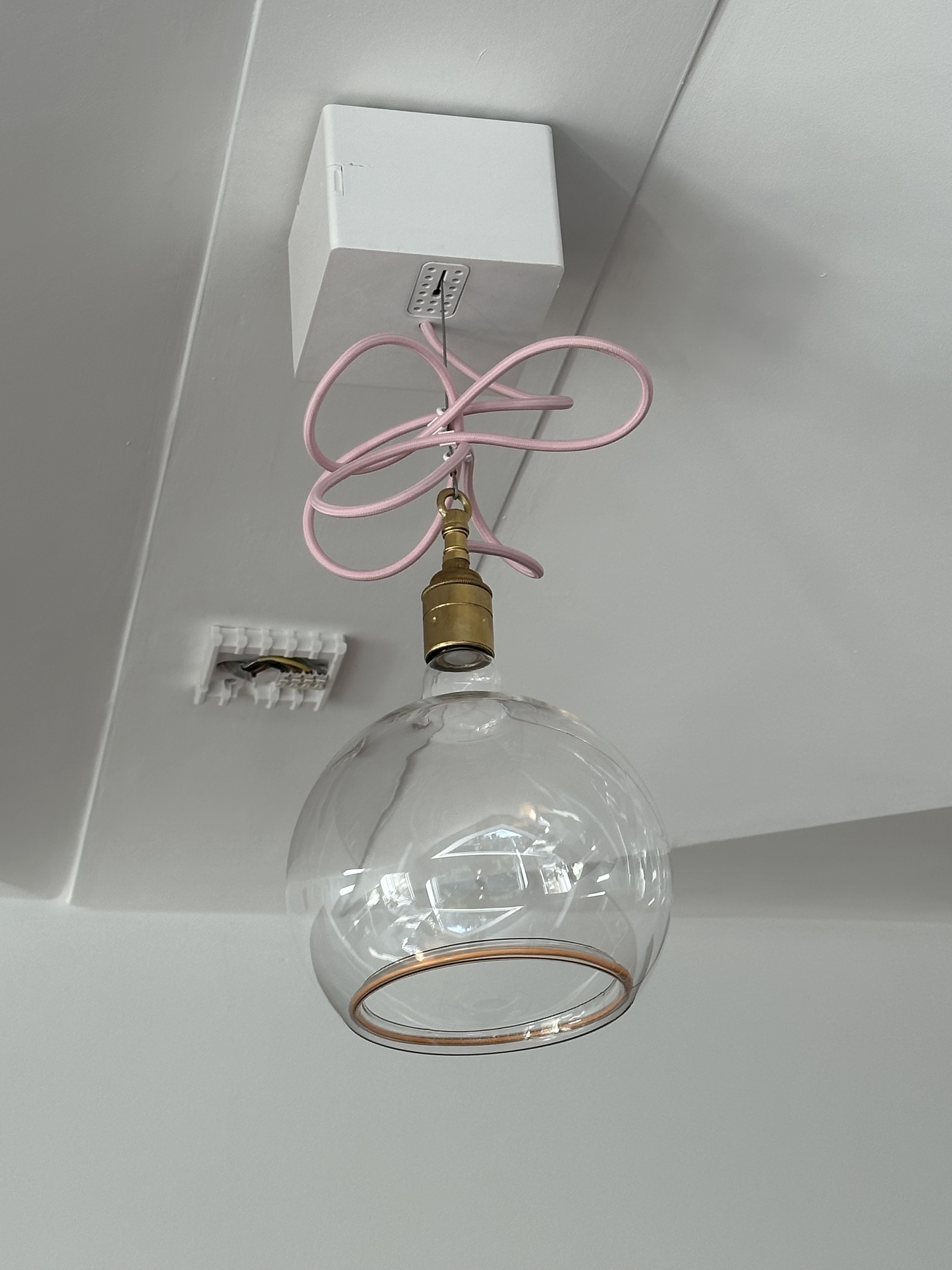
The most recent version of the firmware was uploaded to the devices around two months ago (I know I’ve waffled on about this enough already, but… deployment should not require a step-ladder!). Since then, the units have been through a couple of power cuts, but have otherwise been powered up continuously. They have behaved extremely well, now that I’ve exorcised the gremlins listed above; they smoothly and un-fussily descend on command, usually to appreciative noises from any guests that we happen to be showing off to. I’ve integrated the MQTT topic with our home control software (which definitely needs another blog post at some point), so anyone in the house can drive the Danglepoise from their phone or from the nice Clipsal wall-switches in the dining room.
They look quite nice over the new table, too.
I’m still experimenting with different positions, speeds, and combinations of lamps; there are lots of options, and they’re fun to play with. I’ve built some pre-set patterns into the control software, but being able to fine-tune the lighting based on what we’re doing at the table, whether it’s extended or not, and how many people are seated is surprisingly good fun. At some point, I’ll probably build a proper UI for it so that each lamp can be simply dragged into position on your phone… or possibly even a physical control panel using motorised sliders… hmmm, now there’s a project…
Overall, I’m pleased with how the Danglepoise turned out. I learned a lot, which was fun, and they achieved the desired effect that I was reaching for at the outset. I do have a slight urge to tackle some of the problems encountered above, but it can wait for a while. A few people who’ve seen it have been kind enough to suggest that there might be a market for such a light fitting; I shall have to do more research into this. The idea of a Kickstarter has been mooted. If you think that the world is quite silly enough without such extravagance, do reach out on Mastodon and let me know.